1. Sound power levels of diesel engines of different brands and models
The sound power level of a diesel engine is a core indicator for evaluating its noise performance. Relevant domestic and international standards—such as GB 14097-1999 “Noise Limits for Small and Medium Power Diesel Engines”, GB/T 14097-2018 “Noise Power Level Limits for Reciprocating Diesel Generator Sets”, and GB 11871-2009 “Airborne Noise Limits for Marine Diesel Engines”—all specify the sound power level of diesel engines.
The table below summarizes the noise data for some typical diesel engine models:
Brand |
Model |
Configuration |
Common‑use Power (kW) |
Sound Pressure Level of Noise (dB(A)) |
Measuring Distance |
| Cummins | QSX15‑G8 | 6‑cylinder In‑line | Approx. 340 (genset) | 93‑106 | 7 m beside the genset |
| Cummins | KTA50‑G3 | 16‑cylinder V‑type | 1000 (genset) | 93‑106 | 7 m beside the genset |
| Volvo | TAD843GE | 6‑cylinder In‑line | 260 (genset) | 103 | 7 m beside the genset |
| MTU | 12V2000G25 | 12‑cylinder V‑type | 500 (genset) | 98‑105 | 7 m beside the genset |
| MTU | 12V2000G85 | 12‑cylinder V‑type | Approx. 800 (genset) | 98‑110 | 7 m beside the genset |
| Weichai | WP13D385E310 | 6‑cylinder In‑line | 350 | Approx. 110 | 7 m beside the genset |
| Weichai | 8M33D895E310 | 8‑cylinder V‑type | 815 | Approx. 110 | Nominal relative value |
| ——END—— | |||||
2. Estimation of the engine’s overall noise power level
Based on the relationship between sound power level and sound pressure level, under the approximate conditions of a free field (or a large-space semi-free field), the A-weighted sound power level of a diesel engine can be estimated using Lp7m. The estimation formula is:

(Constant correction under semi-free field conditions)
In the formula, the area S = 4πr² / 2 ≈ 4 × 3.14 × 49 / 2 ≈ 307.7 m² is measured using a hemisphere at a distance r = 7 m. Lp7m is the measured sound pressure level at a distance of 7 m from the generator unit.
1. Taking the Cummins QSX15-G8 model (Lp7m = 93 dB(A)) as an example, the corresponding A-weighted sound power level is roughly estimated to be 110±3 dB(A);
2. The A-weighted sound power level of the MTU 12V2000G25 model (Lp7m = 98 dB(A)) is approximately 115±3 dB(A). The estimated A-weighted sound power level of the high-power KTA50-G3 model (Lp7m up to 105 dB(A)) is approximately 120–122 dB(A).
3. The sound pressure level of WP13D385E310 is approximately 110 dB(A), and the corresponding A-weighted sound power level is approximately 122–125 dB(A).
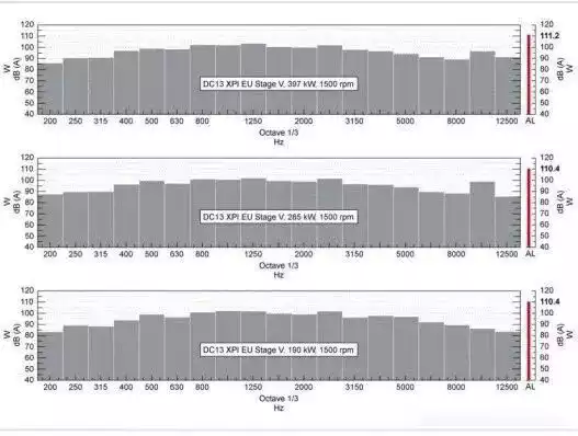
Sound power test data of a 450KW diesel engine
This estimate is for reference only. Accurate data should be based on the sound power level measured strictly in accordance with GB/T 14097-2023.
3. Noise Spectrum Characteristics of Diesel Engines
The noise spectrum of a diesel engine reflects the distribution of sound energy at different frequencies and is an important basis for evaluating noise characteristics and designing noise reduction measures. Based on existing research, the overall noise spectrum of a diesel engine exhibits the following characteristics:
1. Distribution characteristics across the entire frequency band:
The noise energy of diesel engines is mainly distributed in the mid-to-high frequency range. A study of a heavy-duty vehicle diesel engine shows that its noise energy is primarily concentrated in the 1/3 octave band, with a center frequency of 1000–2500 Hz. In the lower frequency range (125–500 Hz), the low-frequency components of combustion noise and piston knocking noise contribute significantly; in the mid-frequency range (500–1000 Hz), fan noise and gear meshing noise begin to appear; and in the high-frequency range (above 1000 Hz), engine block radiated noise and intake/exhaust turbulence noise dominate.
2. Spectral contribution of radiated noise from each component:
When measuring the main components of a diesel engine using the surface acoustic intensity method, the acoustic contributions of components such as the oil pan, valve cover, and air filter differ across different frequency bands. The radiated noise from the oil pan covers a wide frequency band; the radiated noise from the cylinder head cover is mainly in the mid-to-high frequency range; and the gear cover, due to its proximity to the timing gear system, often exhibits a significant meshing frequency peak in the mid-frequency range. Under the condition that the diesel generator set operates at a constant speed of 1500 r/min, the engine’s fundamental frequency is 25 Hz, and low-frequency components such as the second harmonic 50 Hz occupy a significant position in the overall engine spectrum, but their overall energy proportion is much lower than that of the mid-to-high frequency range.
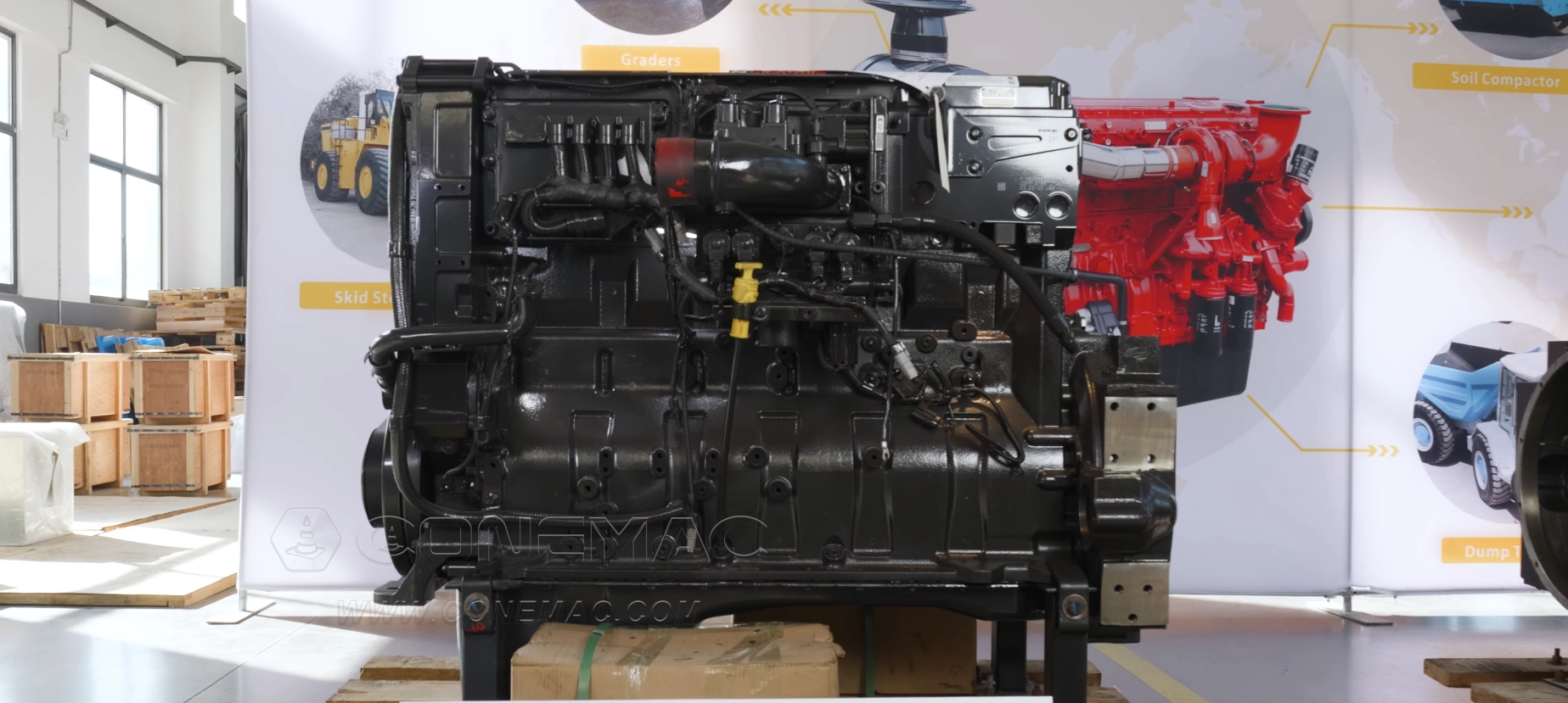
3. Composite noise spectrum of diesel generator set:
The operating noise of a diesel generator set is the result of the superposition of the engine noise, generator noise, cooling fan noise, and exhaust noise, exhibiting typical characteristics of “high-frequency pulsation + low-frequency vibration” composite noise. When the engine’s rated speed is 1500 r/min (25 Hz), the fundamental frequency of a 4-cylinder engine is 50 Hz, and that of a 6-cylinder engine is 75 Hz. The overall noise exhibits prominent line spectrum components at the corresponding fundamental frequency and its harmonic octaves. Simultaneously, the electromagnetic noise generated by the generator rotor rotation (typically concentrated at even-numbered octaves of 100 Hz) superimposed on the engine noise creates a more complex distribution pattern in the frequency spectrum. Identifying the main noise sources during diesel generator set operation should employ spectral analysis and source separation methods, referring to the sound pressure envelope measurement method recommended by ISO 3744 standard, to determine the actual contribution of each noise source in each frequency band.
4. Main frequency range of each noise source:
Combustion noise: Wide frequency band, with energy mainly concentrated in the mid-to-high frequency range (500–4000 Hz).
Piston knocking noise: Primarily mid-to-low frequency (200–1500 Hz), with knocking frequency related to engine speed, number of cylinders, and piston movement frequency.
Valve train noise: Wide frequency band, primarily mid-to-high frequency (500–4000 Hz).
Gear and bearing noise: Primarily mid-to-high frequency, with gear meshing frequencies and their harmonics forming a characteristic spectrum (typical values from several hundred Hz to several kHz).
Intake system noise: Low-frequency components correspond to the engine’s operating cycle frequency, while high-frequency components correspond to airflow turbulence and eddy noise.
Exhaust system noise: Low-frequency components correspond to the exhaust pulse frequency, while mid-to-high frequency components correspond to high-speed airflow injection and turbulence noise.
Fan system noise: The blade passing frequency forms a significant mid-to-low frequency spectrum.
Main body radiated noise: The combined sound radiation resulting from the convergence of various excitation forces on the engine surface after structural transmission. Thin-walled components such as the oil pan exhibit broadband radiated noise due to their high modal density.
Conclusion
Accurately identifying the noise sources and intensity of diesel engines is the technical foundation for reducing the overall noise level of diesel generator sets and designing effective noise reduction solutions. Throughout the entire engine noise control process, the noise sources contributing the most noise (generally in the order of exhaust noise, combustion noise, engine block radiated noise, and fan noise) should be prioritized and addressed with step-by-step solutions. Exhaust noise is controlled through high-performance mufflers, combustion noise is reduced by optimizing combustion system parameters, engine block radiated noise is suppressed through the addition of damping layers and structural optimization, and fan noise is reduced through low-speed design or temperature-controlled variable-speed fans. Simultaneously, accurately determining the contribution of each noise source through spectrum analysis under constant speed conditions is a scientific guarantee for effectively implementing precise noise reduction strategies from the source to the propagation path.